Growbox CM5 Board
The I/O board with the computer on it: a Raspberry Pi Compute Module 5 replaces the ribbon cable to a Pi 5, and one 12 V supply runs everything. Same sensors, strips, actuators, heaters and GPIOs as the I/O board, so the growbox software doesn't change and the chamber sensor boards plug in as they are.
- 221 parts
- 286 nets
- ERC 0 errors
- 190 × 210 mm 4-layer
- case done
- routing done
On the drawer tray
The board sits on the drawer tray in the plywood base, in place of the Pi 5 and breadboard. The tray is 196 mm wide between the foam legs and 311 mm deep, with 56 mm of headroom, so nothing can plug in from the sides. Every socket opens to the back (towards the back wall's cable gaps and fan), to the front, or straight up for the cables that drop in from the chambers.
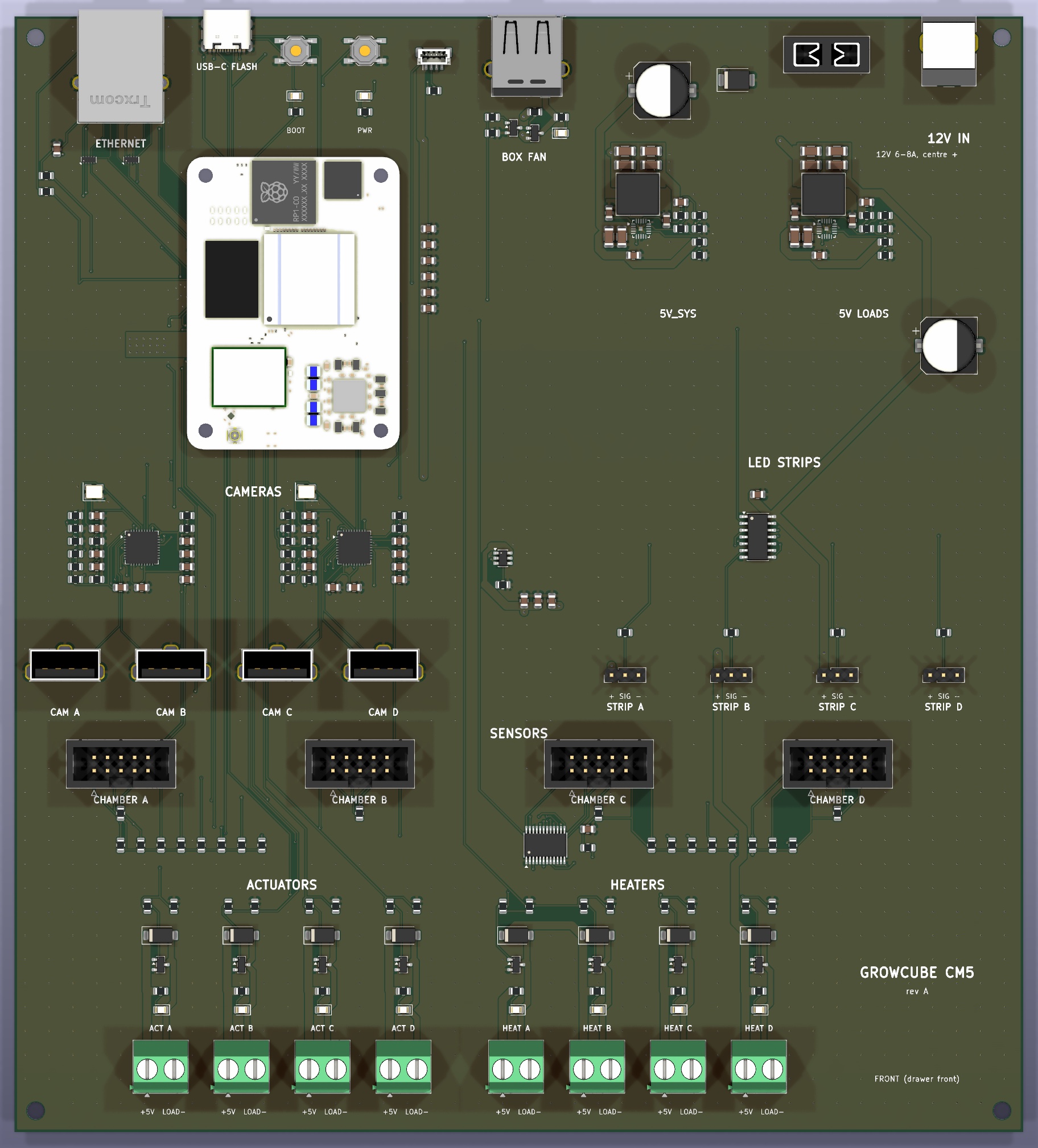
| Edge | Left to right |
|---|---|
| BACK | Ethernet (left cable gap) · USB-C flash · BOOT / PWR buttons and LEDs · CM5 fan · box fan (under the wall fan) · 12 V jack (right cable gap) |
| UP | 4 camera sockets · 4 LED strip headers (+ SIG −) · 4 chamber ribbons |
| FRONT | 4 actuator and 4 heater screw terminals, screws reached from above with the drawer out |
3D-printed case
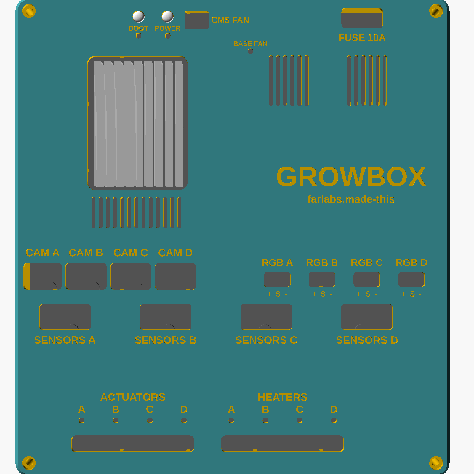
A lid and a base plate that close the board in on the drawer tray and leave everything you touch open. Every opening has its name debossed beside it, every LED has a light hole, the Compute Module 5 is open for its cooler, and the converters sit under vent grilles. It's generated from the board's real part positions, so it moves with the board.
| Where | What's open |
|---|---|
| TOP | CM5 and its cooler · CAM A–D · RGB A–D (+ S −) · SENSORS A–D · CM5 fan · fuse · BOOT / POWER buttons · light holes for the actuator, heater and base-fan LEDs · screwdriver openings over the terminals · vent grilles |
| BACK | Ethernet · PROG (USB-C) · BASE FAN · 12V IN, labelled on the wall · exhaust slots behind the CM5 |
| FRONT | wire slots for the actuator and heater terminals |
| RIGHT | P4S, FarLabs and made-this, debossed |
Built for strength
- 3 mm top with 4 mm ribs underneath on a 30 mm grid.
- 12 pillars under the lid, each landing on bare board with a support directly below it, so a press goes lid → board → base → tray and never bends the board.
- 33 supports on the 3 mm base plate under everything people push on: the CM5, the buttons, every socket and header, every screw terminal.
- BOOT and POWER are captive printed plungers in guide tubes, so they can't fall out or be pushed through.
Printing
- Lid top-down (the labels face the bed); base plate flat; the two buttons upright.
- PETG, 0.2 mm layers, 4 walls, about 30% infill.
- Pillars and supports stop 0.1–0.2 mm short of the board, so check the fit on the first print.
- Files in the repo's case/ folder: growcube-cm5-case.stl, growcube-cm5-base.stl, growcube-cm5-buttons.stl.
Power
What connects to the CM5
Connectors
| On the board | What plugs in |
|---|---|
| 12 V IN | barrel plug 5.5 × 2.1 mm, centre positive; 12 V 6 A (72 W) supply |
| CAMERA A–D | 4 × USB-A, the existing USB cameras |
| ETHERNET | RJ45, Gigabit |
| USB-C | a laptop, only for flashing the CM5's eMMC |
| CHAMBER A–D | 10-way ribbons to the chamber sensor boards (unchanged) |
| STRIP A–D | 3-way Dupont plugs: + SIG − |
| ACT / HEAT | screw terminals: +5V and LOAD− |
| BOX FAN | USB-A, the 60 mm box fan |
| CM5 FAN | JST-SH 4-pin, the CM5 heatsink fan |
Power budget at 12 V
| Rail | Typical | Peak |
|---|---|---|
| CM5 | 1.5–2.5 A | 5 A |
| Hubs + 4 cameras | ~1 A | 2 A |
| Strips, actuators, heaters, box fan | 3–5 A | 8 A |
| 12 V input (90% efficient) | 2.5–4 A | ~7 A |
A 12 V 6 A supply covers normal running with the heaters pulsed one at a time. The jack is rated 8 A and the fuse 10 A, so a 12 V 8 A supply gives full headroom.
Decided
- One 12 V input with two on-board 5 V converters (TI TPS568230, values from TI's datasheet).
- Four USB-A camera sockets through two USB2514B hubs.
- Gigabit Ethernet, wired as on Raspberry Pi's own CM5 IO board.
- CM5 with eMMC; flashed over USB-C with the RPIBOOT button.
- Box fan socket on GPIO 12, also added to the ribbon I/O board.
- The CM5's 5 V pins sit in a solid copper patch with 18 vias to the 5 V plane below, sized for the up to 5 A the module can draw.
Still open
- A microSD slot, so the cheaper CM5 Lite would also work.
- Converter and hub values reviewed against the datasheets' layout examples before ordering.
Cost, assembled by JLCPCB (AUD)
Option C on the cost page: the Compute Module 5 plugs onto this board, which does everything.
| Item | 1 growbox | each, of 6 | Notes |
|---|---|---|---|
| Board printed and assembled | A$389 | A$131 | 4 layers, impedance-controlled, 0.3 mm vias. 5 printed, 2 assembled (one spare); the Ethernet jack is bought and soldered by hand |
| Chamber sensor boards ×4 | A$52 | A$13 | same boards as option B |
| Compute Module 5 (4 GB, 32 GB eMMC) | A$144 | A$144 | 2 GB / 16 GB saves about A$38 |
| CM5 heatsink and fan | A$15 | A$15 | |
| Power supply, 12 V 8 A | A$33 | A$33 | runs everything |
| Electronics total | A$633 | A$336 | per growbox; shipping is on the cost page |
The two board lines are real costs for these exact designs: JLCPCB's quote for the bare boards, live part prices and its published assembly fees, on 3 October 2026. The rest are typical online prices. All in Australian dollars, US prices at about A$1.52 per US$1. The whole growbox, with the box, base, cameras, lights and heaters, is on growcube.p4s.space/cost.
Where this is
Schematic
Generated from circuit.py, electrical rule check 0 errors.
Placement
Sized and laid out for the drawer tray; no overlaps or shorts in the design rule check.
Case
Lid, base plate and captive buttons, generated from the board.
Routing
Four layers, USB and Ethernet at controlled impedance, every connection made: no open connections or electrical errors in the design rule check.
Order files
Gerbers, bill of materials and placement file for JLCPCB, every part matched to a stocked LCSC number. The Ethernet jack is hand-soldered.