Growbox I/O Board
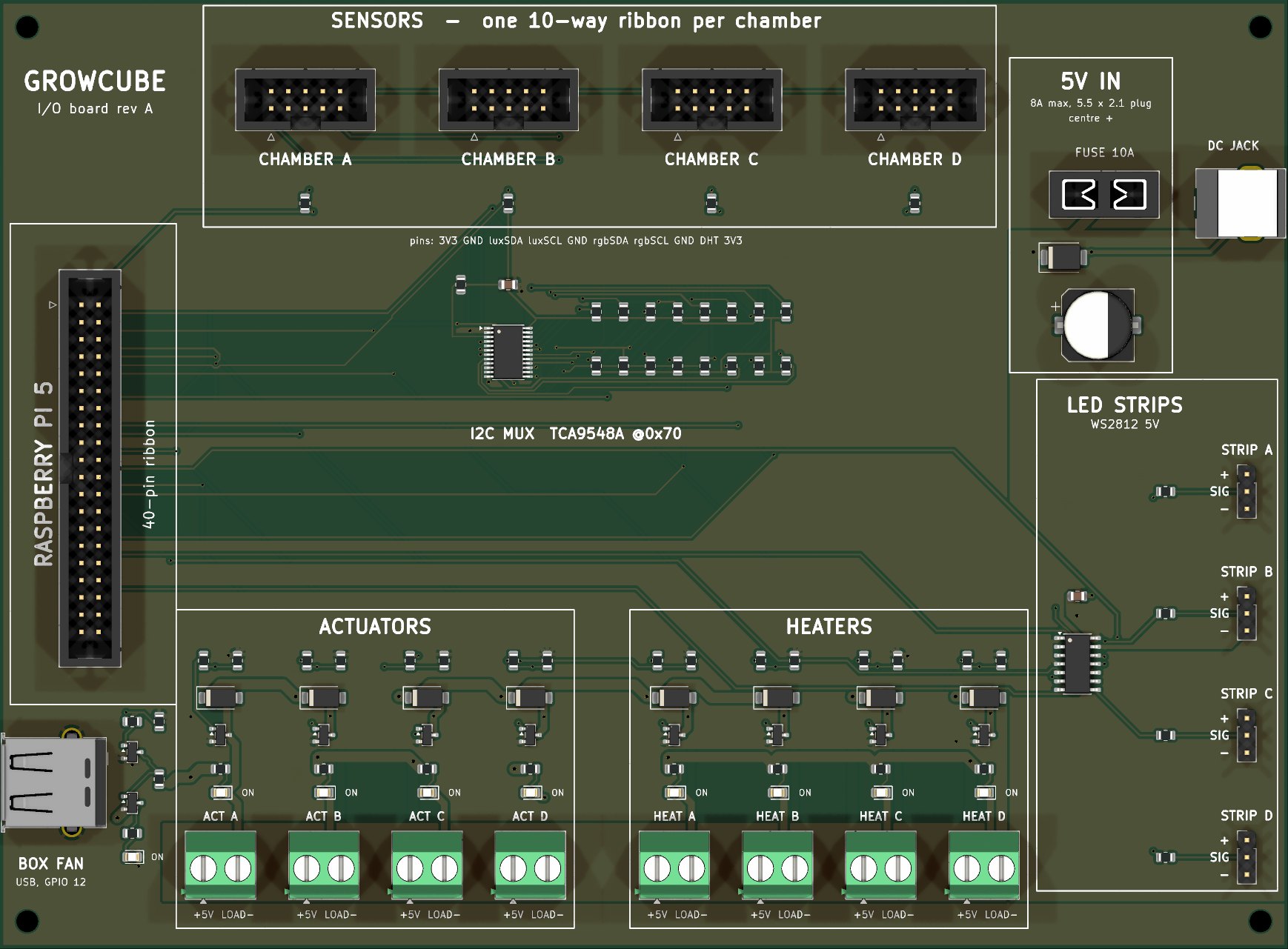
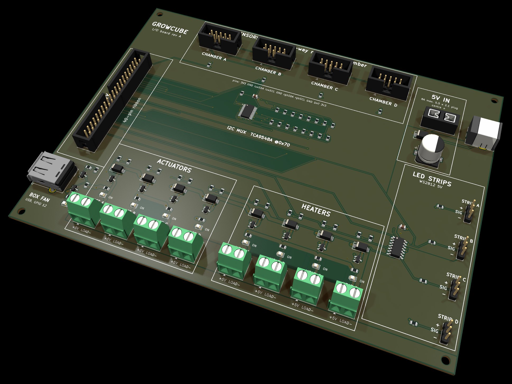
One board between the Raspberry Pi and the four chambers, replacing the breadboards. Click a zone on the board, or a label underneath it, to see what plugs in there and what each pin carries. There's also an option with the computer on the board: the CM5 board.
- 190 × 140 mm 2-layer
- 110 parts
- 76 nets
- fully routed
- ERC / DRC 0 errors
- + 4× chamber sensor boards
Power budget
Everything runs from the one barrel jack, rated 8 A. The heaters only nudge each chamber by 1–2 °C over long periods, so the software pulses them one at a time. A PTC element is either on (about 1.6 A, self-limited near 100 °C) or off, and the duty cycle sets the average heat.
No board change is needed for this: same MOSFETs, terminals and 10 A fuse. Running all four heaters together would use 6.4 A of the 8, so the software should keep them staggered.
Chamber sensor board
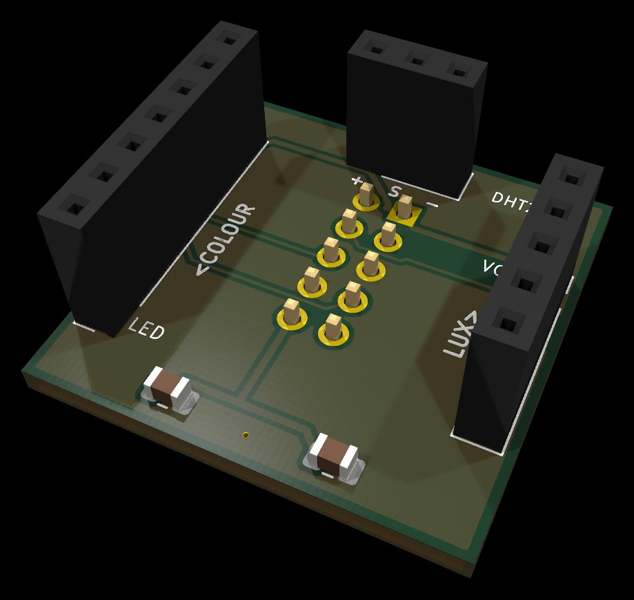
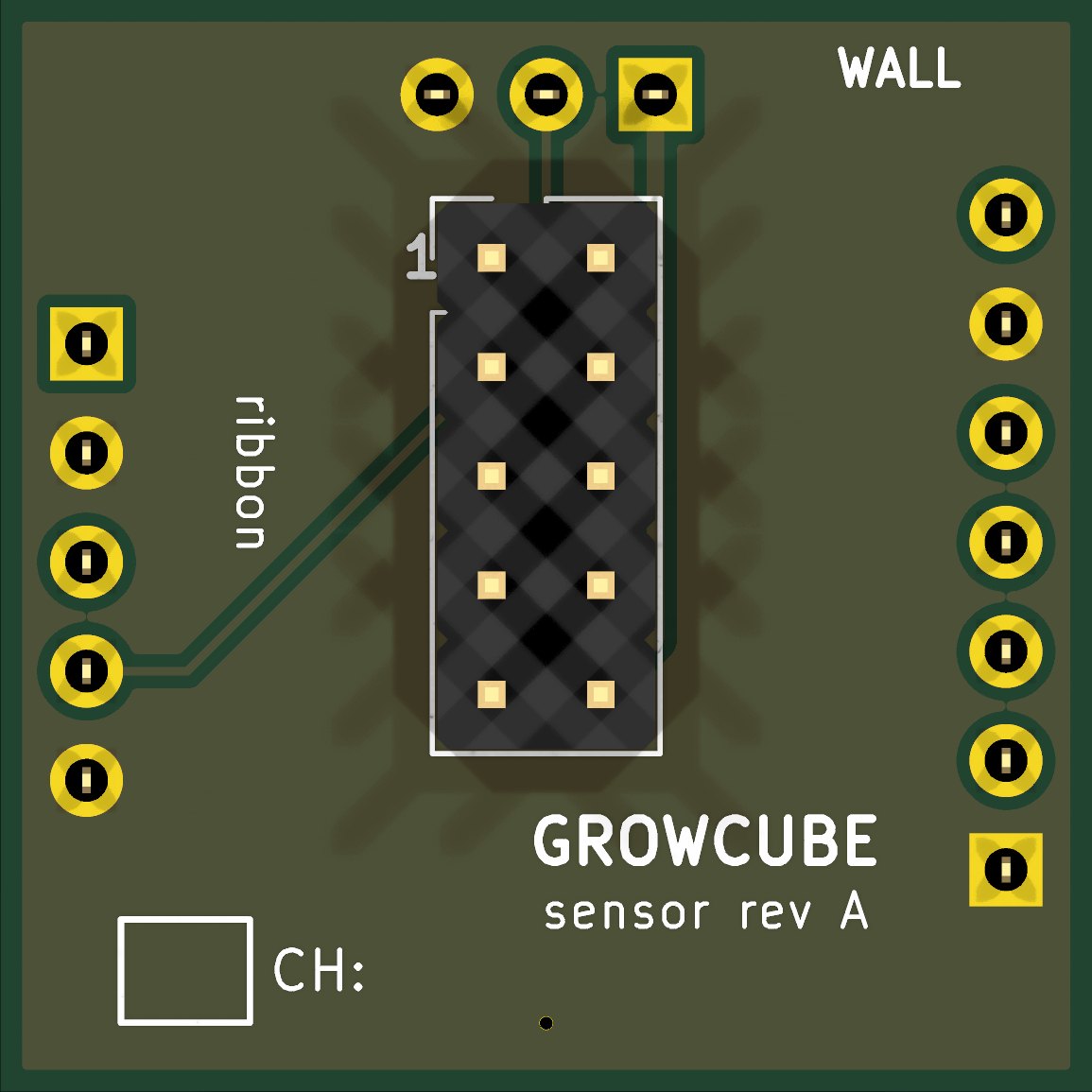
A 25.4 mm square that lies flat on each chamber floor against the wall, where the box design already reserves it. The three sensor modules plug into sockets with the pins they came with, so a faulty one swaps out without soldering. The ribbon from the main board plugs in underneath and drops straight down the notch.
| Socket | Pins, in order | On the board |
|---|---|---|
| COLOUR | LED INT SDA SCL 3V3 GND VIN | LED tied low (module's white LED off), VIN gets 3.3 V, INT and 3V3 unused |
| LUX | VCC GND SCL SDA ADDR | ADDR tied low: address 0x23 |
| DHT22 | + SIG − | sensor faces into the chamber |
| RIBBON | 2×5, underside | same pinout as the main board's chamber header |
- The light sensors sit about 10 mm up, so the dish holder's 2.4 mm plate slides underneath.
- Front-wall and back-wall chambers use the same board, turned round.
- Plug the ribbon either way round and nothing shorts: wires 1 and 10 are both 3.3 V.
- The I2C bus will run at half speed (50 kHz) for the long ribbons: one line in the Pi's config.txt.
- The box's notch plug needs a pocket for the ribbon plug; that goes in the box drawings next.
Cost, assembled by JLCPCB (AUD)
Option B on the cost page: a Raspberry Pi 5 next to this board on a ribbon cable.
| Item | 1 growbox | each, of 6 | Notes |
|---|---|---|---|
| Board printed and assembled | A$206 | A$55 | 2 layers, 2 oz copper. 5 printed, 2 assembled (one spare) |
| Chamber sensor boards ×4 | A$52 | A$13 | 5 printed and assembled; mostly JLCPCB's fixed fees |
| Computer: Raspberry Pi 5, 1 GB | A$70 | A$70 | 4 GB adds about A$40 |
| Pi 5 cooler and 32 GB microSD | A$21 | A$21 | |
| Power supplies | A$50 | A$50 | Pi 5 27 W USB-C (A$20) + 5 V 10 A for the loads (A$30) |
| 40-way ribbon cable | A$5 | A$5 | |
| Electronics total | A$404 | A$214 | per growbox; shipping is on the cost page |
The two board lines are real costs for these exact designs: JLCPCB's quote for the bare boards, live part prices and its published assembly fees, on 3 October 2026. The rest are typical online prices. All in Australian dollars, US prices at about A$1.52 per US$1. The whole growbox, with the box, base, cameras, lights and heaters, is on growcube.p4s.space/cost.
Where this is
Schematic
Generated from circuit.py. Electrical rule check passes.
Placement
Every part placed in its zone and labelled on the silkscreen, on both boards.
Routing
Autorouted with Freerouting: 1.5 mm 5 V tracks, 1 mm load tracks, ground on both layers. Design rule check: 0 errors.
Order files
Gerbers, bill of materials and placement file for JLCPCB, for both boards, every part matched to a stocked LCSC number.