Build a growbox
A foam box with a camera in the lid. A Raspberry Pi Zero 2 W takes a photo of the plant every few minutes, the coloured lights help it grow, and three sensors measure the temperature, the humidity and the light. Students build it on breadboards. The only soldering is the pins on two sensors, which a teacher does once.
Tap a part to pick it out in the 3D model. Everything else fades back.
How it works
Everything electrical lives on the lid. The door at the front lifts out, so students can get to the plants without touching the wiring.
On the lid
The Pi Zero 2 W and the big breadboard. A T-shaped Raspberry Pi breakout board (often called a T-Cobbler) brings all 40 Pi pins onto the breadboard. The camera points down through a square hole in the middle.
Under the lid
A sturdy printed rack hangs on four posts and holds a strip of 20 RGB LEDs about 50 mm above the plant, angled 20° in towards it, so they grow it well at gentle power. The rack also guides the sensor ribbon and the heater cable, so nothing tangles. They shine red and blue (purple light), which is the light plants use most. We never use white: it draws the most current.
Inside the box
The plant tray on the floor. A small breadboard of sensors on the back wall, with the two light sensors sticking out facing up. A 60 °C heater on the left wall by the door, well away from the sensors. One 10-wire ribbon joins the sensors to the lid.
The foam pieces
One growbox is seven pieces of 20 mm foam. Your teacher cuts them out. Tabs on the walls push into slots in the floor and the lid, so there's no glue. All sizes are in millimetres.
Printed parts
PLA, 0.2 mm layers, 15% infill, no supports. Print the camera sleeve first: test it in the lid hole before you print the rest.
| Part | What it does | Print time | Download |
|---|---|---|---|
| Light rack | A 12 mm ring on four 10 mm posts. The LED strip sticks on its underside, which slopes 20° so the lights point at the dish. Built in: a short guide for the rainbow ribbon, and two pairs of small wire loops, one for the LED lead and one for the heater cable. Four pegs push up into the lid. | ~2 h 30 m | .stl |
| Camera sleeve | Pushes up into the lid's square hole from below and holds the camera, lens down. | ~20 m | .stl |
| Plant tray | Holds a 90 mm petri dish in the same place every time, so photos line up. Catches spills. Slides out through the door. | ~1 h 40 m | .stl |
| Heater cradle | Pegs into the left wall, near the door. The heater slides in from the top and sits 8 mm off the foam. | ~35 m | .stl |
| Door handle | Two pegs push into the door face. | ~25 m | .stl |
Build it
Ten steps over about three lessons, then plan your experiment. Steps 1–3 can happen while the parts print.
Cut the box
Cut the seven foam pieces and the plywood deck from the DXF files. Sand any rough edges lightly with fine sandpaper.
Teacher, or students with supervision · 20 min per box
Push the walls into the floor
- Stand the left and right walls in the floor's side slots. The long edge goes front to back.
- Drop the back wall in between them, into the two back slots.
- Press down until the tabs are flush with the bottom of the floor.
No glue. The walls only stay square once the lid is on, so don't worry if they wobble now.Make the door
Glue the door plug (120 × 120) to the middle of the door face (160 × 120) with PVA, with the bottom edges level. Push the printed handle's pegs into the face. Let the glue dry overnight.
Foam-safe glue only. PVA or low-temperature hot glue. Spray glue and superglue melt polystyrene.Glue the deck to the lid
Line up the holes in the plywood deck with the holes in the foam lid and glue them together with PVA. The engraved rectangles show where the breadboard and the Pi go.
Fit the lights and the camera
- Push the camera sleeve up into the lid's square hole from underneath. Drop the camera in from the top, lens down, with its flat cable coming up out of the sleeve. You'll plug that cable into the Pi in the next step.
- Cut a 20-LED length from the RGB LED strip (cut only across the copper pads). Keep the end with the plug.
- Stick the strip round the sloping underside of the light rack, 5 LEDs to a side, starting at the front-right corner. Fold it at each corner: fold back over itself, then fold again at 45°.
- Thread the strip's lead up through the two loops on the front-right post. On the lid it comes out of its hole just behind the LED terminal (J1).
- Push the rack up under the lid so its four pegs go into the peg holes.
Mount the Pi and the breadboard
Screw the Pi Zero 2 W onto the deck's back-left corner with nylon standoffs, ports facing the back. Before you peel anything, turn the big breadboard the right way round: column 1 at the left end (by the Pi's corner) and row a along the front, nearest the door, with row j at the back. Facing the door, the numbers 1, 5, 10… should read left to right along the board. Stuck on backwards, every hole in the wiring steps is in the wrong place, so check with a partner first. Then peel the backing off and stick it on its rectangle. Plug the T-shaped Pi breakout board in at the left end. Join it to the Pi with the 40-wire ribbon: run it straight forward from the Pi, fold it once at 45° over the breakout board, and push it down into the socket. The stripe on the ribbon is pin 1.
Then plug in the camera: gently lift the little black latch on the Pi Zero's camera socket (the narrow one at the right-hand end), slide the camera's flat cable in with its shiny contacts facing the board, and press the latch back down.
Wire the big breadboard
Work through the Breadboard assembly page. Its steps 1–12 wire this big breadboard; steps 13–17 build the sensor board in the next step. Each one adds a few pieces, explains why they're there, and shows exactly where they go in 3D.
Never join the Pi's 5 V pins to the breadboard. The breadboard power module powers the lights and the heater. The Pi has its own supply. Only the grounds (black) are joined.Build the sensor board
- Teacher: solder right-angle pins onto the BH1750 and the TCS34725, so they stick out of the board facing up. The 3D reference below shows what they should look like: the long ends of the pins point straight out from the edge, level with the board.
- The DHT11 (temperature and humidity) comes with its straight pins already fitted, so it needs no soldering. It plugs into row f and hangs down over the middle gap.
- Wire the small breadboard: Breadboard assembly, steps 13–17.
- Stick it on the inside of the back wall, centred, with its bottom edge 2 mm above the floor. Seen from the door: column 1 on the left, row a at the bottom (where the sensors are) and row j at the top, nearest the lid.
- Push the heater into its cradle and the cradle's pegs into the left wall, near the door, below the rack's heater loops.
Reference · drag to turnJoin the lid to the box
- If the ribbon's top end is still plugged into the big breadboard from the assembly steps, unplug it. Feed the 10-wire ribbon up through the rack's short guide and the lid's slot, and thread the heater wires up through the two loops on the rack's front-left post and out of the lid's heater hole.
- Lower the lid so the six wall tabs go into its slots. Press it down evenly.
- Plug the ribbon back into the big breadboard: row c, columns 25–34, brown wire in column 25.
- Screw the heater's two wires into J2 (row h, columns 31–32). It doesn't mind which way round. Tighten the screws and give each wire a gentle tug.
Reference · drag to turnCheck, then power up
- A partner checks every wire against the Breadboard assembly steps before anything is plugged in.
- Power module: the back jumper is on 5 V, and nothing is plugged into the front red + rail.
- Plug in the Pi's supply first, then the breadboard supply.
- Slide the tray in with your plants in their petri dish. Push the door in.
Software comes later. The Pi will run a small web page on the school network. This build book covers the hardware only.Plan your experiment
With your class, plan a controlled experiment on the Experimental design page: choose the one variable to change across the four growboxes, and which growbox is yours. Then set your growbox in Your settings.
Safety rules for the class
Breadboard assembly, step by step
Build both breadboards one step at a time. Each step shows the pieces you need, what they're for, and exactly where they go. Turn the 3D board to see each wire. New pieces drop in, then the circuit lights up to show where the electricity flows.
What you'll learn, in order
Each step adds one big idea. Click a step to jump to it, or use the arrow keys.
Experimental design
Plan your class's controlled experiment, then set your growbox.
Under development
The planning activities for this page are still being written. For now, make your class plan here, then go to Your settings.
Your class plan
Your class changes one variable: each growbox gets a different value of it. Everything else stays the same in every growbox: those are the controlled variables.
Your settings
Your growbox's day: the settings it will keep for your experiment. Check them, then copy them to apply to your growbox when it's connected.
Your growbox's day
Plan one day. Your growbox repeats it every day of your experiment. Change only your class's variable; the rest are controlled variables, the same as the other groups.
Or mix your own:
Your light: Purple
For teachers
Everything a teacher needs to run the student growbox with a Year 7–8 class. Start with the risk assessment and the costs, so you can get approval and order the parts. Then work through the five jobs in Before class (cutting, soldering, setting up the microSD cards and checking the Wi-Fi) before your students start building.
Risk assessment
For a Year 7–8 class building and running the student growbox. Check it against your school's own policies and templates, and add anything particular to your room.
| Hazard | What could happen | Before | Controls | After |
|---|---|---|---|---|
| Soldering ironTeacher only, before class | Burns from the 350 °C tip; a dropped iron starting a fire. | Medium |
| Low |
| Solder fumesTeacher only | Breathing in flux fumes. | Medium |
| Low |
| Cutting the foam and the plyTeacher or technician | Fumes from hot-wire or laser cutting; cuts. | Medium |
| Low |
| Hand toolsStudents | Cuts or pinches from side cutters and wire strippers; flying wire offcuts. | Medium |
| Low |
| Electrical: wiring mistakesStudents | A short circuit makes a part or wire hot. | Medium |
| Low |
| Electrical: mainsEveryone | Shock from a damaged charger or lead. | Medium |
| Low |
| HeaterStudents | Touching the heater while it's on. | Low |
| Low |
| Water near electronicsStudents | Spills reaching the boards or the charger. | Medium |
| Low |
| Plants and pond waterStudents | Germs from pond water or duckweed. | Low |
| Low |
| Bright lightsStudents | Eye discomfort from looking into the LEDs. | Low |
| Low |
| CablesEveryone | Tripping over power leads. | Low |
| Low |
| Wi-Fi passwordSchool network | The network password shared further than it should be. | Low |
| Low |
Costs and parts
Prices in Australian dollars including GST, checked on 4 October 2026. The Pi and the camera are Core Electronics prices. The rest are typical Australian retail prices. Check before you order.
| Have | Item | What it's for | Buy from | Each | 1 kit | Class set (4) |
|---|
Tools you'll need (not in the price)
A 3D printer, a way to cut foam (CNC hot wire, CNC router or laser), a laser cutter for the ply deck, a small Phillips screwdriver for the screw terminals, side cutters and a wire stripper.
Ways to spend less
The camera is the most expensive part. A generic 5 MP OV5647 camera for the Pi Zero costs about A$15 (it saves A$33), but you have to twist the lens by hand to focus at 11 cm. AliExpress prices for the sensors, cobbler and power module are about half, with two to four weeks of shipping.
Before class
Cut the foam
Teacher or technician · on a CNC hot-wire cutter, CNC router or laser cutter
Two boxes fit on one 1200 × 600 × 20 mm sheet of expanded polystyrene (EPS). All sizes are in millimetres. Slots are cut the same size as the tabs: foam squashes, so they push in tight.
Safety. Laser cutting polystyrene melts it, gives off styrene fumes and can catch fire. Many schools don't allow it. A CNC hot-wire cutter or a CNC router with a sharp bit is safer. If you do laser cut, use full extraction, low power and many passes, and never leave the laser.Teacher tip. Cut one test tab and slot first. If the tab is loose, make the slots 0.5 mm smaller in your CAM program. If it's too tight to push in, make them 0.5 mm bigger. The DXF uses one layer called CUT for every cut line.Laser-cut the lid deck
Teacher or technician · laser cutter · about 10 minutes a deck
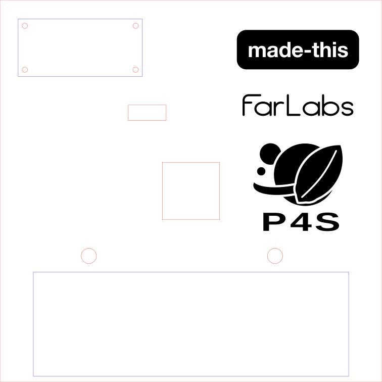
A 200 × 200 mm square of 3 mm plywood, glued on top of the foam lid. The Pi and the big breadboard sit on it, and the laser engraves the made-this, FarLabs and Plants for Space marks on its open corner.
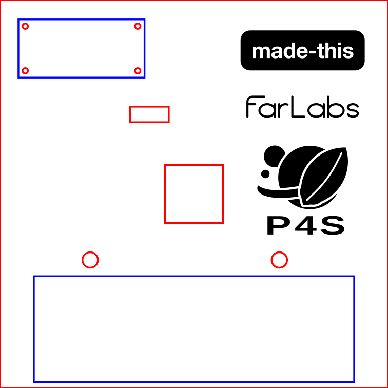
- Red lines: cut right through. The camera hole, the LED and heater lead holes, the ribbon slot, the four Pi screw holes and the outside edge.
- Blue lines: a light line engrave, marking where the breadboard and the Pi go.
- Black shapes: fill-engrave. The three marks.
Teacher tip. In the DXF, set the ENGRAVE layer to fill-engrave and the CUT layer to cut. Engrave first, then cut, so the deck doesn't move. Glue it to the lid with PVA, lined up with the camera hole.Solder the light sensors' pins
Teacher · about 15 minutes a kit · 12 joints
Two of the three sensors come without pins. Solder right-angle pins onto them once, and students can push them into the breadboard like everything else. Students don't solder in this build.
BH1750 light sensor (GY-302) + 5 pinsTCS34725 colour sensor + 7 pinsRight-angle header strip, 40 pinsDHT11: pins already fittedBack: as they come · Front: soldered · drag to turn- Snap a 5-pin and a 7-pin piece off the header strip.
- Push the short ends down through the holes from the top of the board, the side with the chip. The long ends point straight out past the edge, level with the board. A blob of Blu Tack holds them while you turn it over.
- Solder one end pin, check the strip is square, then solder the rest. A good joint is a small shiny cone with no solder bridging to the next pin.
- Plug both into a spare breadboard to check they fit.
Use lead-free solder, a fume extractor or an open window, and the iron's stand. Wash your hands afterwards.Put growbox OS on the microSD card
Teacher · about 10 minutes a card · once per kit
growbox OS is the software for the Pi: it runs the lights, the heater, the sensors and the camera, and serves the growbox dashboard.
Download growbox OSComing soon- Install Raspberry Pi Imager on a computer (Windows, Mac or Linux).
- Put the 32 GB microSD card into the computer, using an SD adapter or a USB card reader.
- In Imager, choose Raspberry Pi Zero 2 W as the device.
- For the operating system, scroll down to Use custom and pick the growbox OS file you downloaded. You don't need to unzip it.
- For storage, pick the microSD card. Check the size is right: everything on the card is erased.
- When Imager asks about OS customisation, choose No. The growbox gets its Wi-Fi from Device connection on this page.
- Wait for it to write and verify, then eject the card. Label the card and its Pi with the same number (Growbox 1, 2, 3, 4).
- Push the card into the Pi Zero, label side out. The first start takes about a minute.
Check the Wi-Fi
Teacher, with your school's IT team · do this a week before
Students connect each growbox to Wi-Fi from Device connection, then open its dashboard from a laptop or tablet. That only works if the network does all four of these:
It MUST have 2.4 GHzThe Pi Zero 2 W only has 2.4 GHz Wi-Fi. It can't see a 5 GHz-only network at all. A network that offers both bands under one name is fine, as long as 2.4 GHz is switched on.
Devices MUST be able to reach each otherThe dashboard comes straight from the growbox, so a student's laptop has to be able to reach it on the network. Networks with "client isolation" or "AP isolation", which most guest networks have, block this.
A name and a passwordWPA2-Personal: one shared password. Networks where everyone logs in with their own username (WPA2-Enterprise) or a sign-in web page won't work.
Everyone on the same networkThe growboxes and the students' laptops or tablets have to be on the same Wi-Fi network.
What to ask IT: "We have four Raspberry Pi Zero 2 W devices for a science project. Can we have a WPA2-Personal network with 2.4 GHz on, where student devices can reach the Pis directly (no client isolation) on port 7979?" If the school network can't, a small travel router in the classroom works: connect the growboxes and the students' devices to it.The Connect button uses Bluetooth, which works in Chrome or Edge on a laptop, Chromebook or Android tablet. iPads can't do the Bluetooth step, but they can open a growbox's dashboard once someone else has connected it. Type the Wi-Fi password yourself rather than giving it to students.
Extra information
Power
Chip design: check your wiring
Finished the breadboard assembly? Check your work here before you plug anything in. Compare your two boards with these diagrams, one wire at a time.
Check the big breadboard, on the lid
Hover over a wire to light it up, then find the same wire on your board. Check both ends: the right row letter and the right column number. Short wires lie flat on the board; tall wires arch over from the Pi breakout board.
Check the sensor breadboard, on the back wall
Check the ribbon is in row h with brown in column 2, the two light sensors are along row a, and the DHT11 is in row f, hanging over the middle gap. Then check every short wire, both ends.
Check it in 3D
Turn this model to match your board, then compare. Switch off the tall wires to check the flat ones underneath, or switch off the parts to see every wire's ends.
Check the Pi's pins
Each job uses one GPIO pin. Check each tall wire starts at the right label on the breakout board.
| Job | GPIO |
|---|
What is a growbox?
A growbox is a small box where you control everything a plant feels: how bright the light is, what colour it is, how many hours a day it's on, and how warm it is. You'll build one, then use it to find out what makes plants grow.
A controlled experiment in a box
Outside, the weather, the season and the shade all change at once, so you can't tell which one made a plant grow. In a controlled experiment you change just one variable and hold the others steady. A growbox lets you do that.
The variable you change
The light's colour, how many hours a day it's on, or how warm the box is: one of them, different in each growbox.
Controlled variables
The plants, the water, the box, and every setting you aren't testing stay the same in every growbox.
What you measure
The camera takes a photo every few minutes, and the sensors record the temperature, the humidity and the light, day and night.
Your class can run four growboxes, each testing something different, and compare what happens.
What the camera sees
Two weeks of duckweed, squeezed into 30 seconds. Each little leaf buds off new ones, so you can count them and see how fast your plants grow.
What you'll do
Build
Put the box together and wire up the lights, sensors and camera on breadboards.
Build book → 2Plan
Choose the one variable your class will change, and which growbox is yours.
Experimental design → 3Grow
Connect your growbox, set the lights and the heater, and watch your plants on the dashboard.
Device connection →Share
Look at your photos and graphs, compare with the other groups, and tell the class what you found.
What you'll learn
How to build circuits
Use breadboards, wires and resistors to connect lights, a heater and three sensors to a Raspberry Pi, a small computer about the size of a stick of chewing gum.
How to read real data
Turn time-lapse photos and graphs of temperature, humidity and light into evidence about how your plants grew.
The build in 40 seconds
Here's everything you'll build, start to finish. Pause it on any step and drag to turn it around.